_edited.png)
TTA - Sometimes it works, sometimes it doesn't - Explained
- Christos Nikolaou
- Apr 21, 2025
- 8 min read
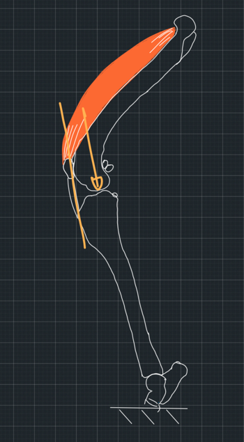
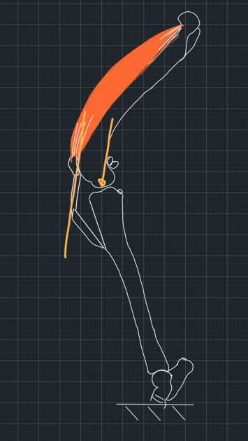
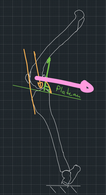
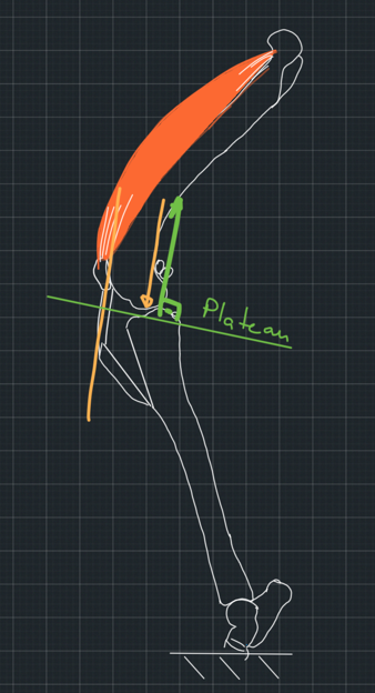
The TTA is based on the assumption that the force from the femur to the tibia and vice versa is approximately parallel to the patellar tendon (Figure 1). It also assumes that the force follows the direction of the patellar tendon. So, if we direct the patellar tendon in a different direction, the tibiofemoral force will follow (Figure 2).
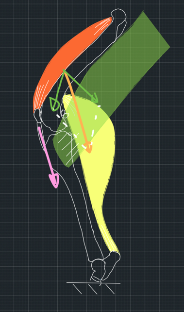
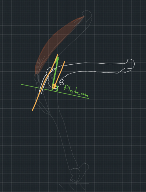
If you think about it for a bit. Let's assume that the tibia is fixed to the ground and the femur is pushed towards it by the force of several muscles which cross the stifle joint. One of these forces, the one generated by the quadriceps muscle, is collinear to the patellar tendon. If the total force is approximately parallel to this force, then all other forces must be in such directions and magnitudes that their sum is parallel to the patellar tendon (Figure 3). This would be a big coincidence, but let's assume this happens.
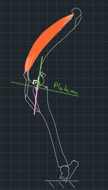
Moving forward, let's consider what happens when the femur applies a force to the tibia, which is parallel to the patellar tendon. To begin with, we will make it easy for ourselves and consider the tibial plateau as a flat surface with no curvature. We will also assume that the contact between the bones is frictionless. When an object pushes on a smooth, flat surface, the surface pushes back with a reaction force that is perpendicular to it. We call a force that is perpendicular to a surface normal to the surface. However, the force the femur applies to the tibia is not normal to the tibial plateau. We assumed it is parallel to the patellar tendon which is at an obtuse angle to the plateau. This means that the two forces, the force from the femur and the reaction force from the tibia will not cancel each other out, and the femur will slip caudally on the tibia in the absence of the cranial cruciate ligament (Figure 4). So far, so good!
Now, I am sure you have already found what we can do to stop the slipping. All we have to do is either change the direction of the tibial plateau, which is what the TPLO technique achieves, or redirect the patellar ligament using the TTA technique. In this post, we talk about the TTA technique. If we make the ligament normal/perpendicular to the tibial plateau, then the force from the femur to the tibia will also be normal to the tibial plateau because we assumed that this force follows the direction of the ligament. Also, the reaction force from the tibia will be normal to the plateau because the plateau is a flat, smooth surface. So, the two forces will cancel each other out. The system will be in equilibrium. Hence, the femur will not slip (Figure 5).
If we begin with such a system in full stifle extension, then as the stifle flexes, the force from the femur to the tibia will tend to have a cranial direction, creating a tendency for cranial slipping, which is prevented by the caudal cruciate ligament (Figure 6).
These are the proposed mechanics of the TTA technique.
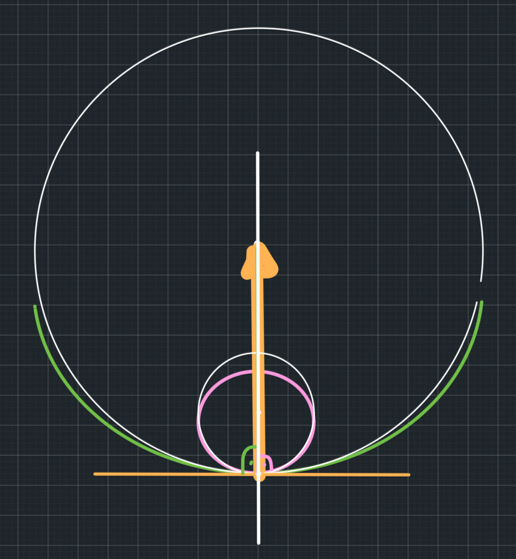
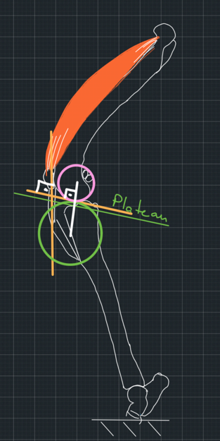
There is only one last detail we need to refine. The tibial plateau is not flat. It is curved. We said that the reaction force from a flat, smooth surface is normal to the surface, but what about the reaction force from a curved surface that is pushed by a curved object? The methodology to find the direction of such a force is the following.
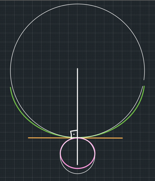
Let's begin with the scenario where one surface is convex and the other one is concave. This resembles the contact between a ball and a bowl. We need to find a circle that will be the best fit for the concave surface of the bowl and another circle that is the best fit for the convex surface of the ball at the point of contact. Then, we will draw the tangent of both circles at this point. This point is common for both circles. So, there will be a common tangent for both circles. We know that a tangent at a point is perpendicular/normal to the radius of the circle through that point. So, the radii of both circles will go through the point of contact, and both will be perpendicular to the tangent through this point. This means that the two radii are in the same line. We call this line, which connects the two circle centres, the common normal. The reaction force from one surface to another will be on that common normal, which is normal to the common tangent (Figure 7).
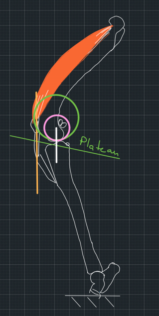
Now, what if the two curved surfaces are both convex, mimicking the contact between two balls? We will do the same. We will draw the line connecting their centres, which is the common normal. It is called that because it is normal to the common tangent (Figure 8).
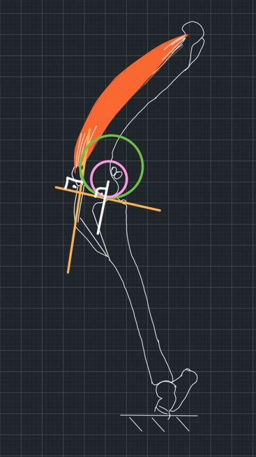
Let's go back to the TTA. When we plan the TTA, we want to re-direct the patellar tendon to be perpendicular to the common tangent. We know that the common normal is also perpendicular to the common tangent. So, both the patellar tendon and the common normal will be normal to the same line. That means that the patellar tendon will be parallel to the common normal. So, essentially, we don't need to draw the common tangent. All we need is the direction of the common normal. The patellar tendon needs to be parallel to that. We said that the reaction force from the tibia will be on the common normal (Figure 9).

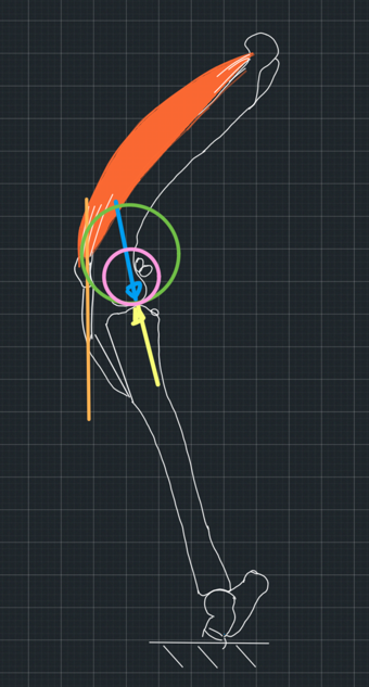
So, we have now achieved the patellar tendon, and hence the force from the femur to the tibia, to be parallel to the reaction force from the tibia to the femur. We have achieved stability (Figure 10).
But let's think for a minute about how we found the common normal. We used the model of a ball contacting another ball. One ball fits the curvature of the femur. What does the other ball represent? The surface of the tibia is concave, not convex. So, what does the circle that we fit on the tibial surface resemble when we plan the procedure?
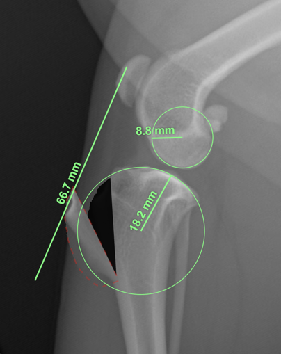
If we look at the tibial plateau from medially to laterally, we will notice that its surface indeed looks like a part of a ball. This is also how it looks on the mediolateral radiographs (Figure 11). However, this curve does not represent the tibial contact surface. This surface is concave. This means that to draw the common normal, we use a surface that does not take part in the contact mechanics of the two bones. So, are we planning to make the patellar tendon perpendicular to a common normal which has a different direction than the joint reaction force, or are we so lucky that we get the correct common normal using the wrong model on a non-existent contact surface?
To make this clear, let's sum up. We assumed that the tibiofemoral force is parallel to the patellar tendon. We also assumed that it would follow the direction of the tendon when we changed it with the TTA technique. Then, we used the method of the common normal to find the direction of the joint reaction force so we can re-direct the patellar tendon to be parallel to it. But to draw the common normal, we used a contact surface that does not exist. So, even if our assumptions on which the TTA mechanics are based are true, we have done the planning wrong.
1. The joint reaction force is parallel to a common normal of two curvatures that do not participate in the contact mechanics of the bone. In this case, we were lucky to find this common normal by drawing one circle to fit the surface of the tibial plateau as shown on the mediolateral radiograph, although this surface is not in contact with the femur. This means that if we had drawn the common normal using the ball-bowl analogue, it would have resulted in the same common normal (Figure 12) as the one we got by using the wrong model (Figure 9). So, the joint reaction force is parallel to the patellar tendon and to a common normal we drew using the wrong model, but it happened to be the correct one. How lucky are we?
2. Although we planned to redirect the patellar tendon to be parallel to the common normal, which we drew using the wrong model, we failed to do this or to execute it accurately (Figure 13).
Our inaccuracy resulted in redirecting the tendon to be parallel to the actual common normal, which we would have found had we used the correct model (Figure 14). In this case, the assumption that the tendon is parallel to the joint reaction force is correct, but we achieved stability purely by luck.
3. The re-direction of the patellar tendon achieves stability even though it is not parallel to the true common normal. This would mean that our assumptions that the tibiofemoral force is parallel to the patellar tendon is not correct. Again, due to luck, we achieved a patellar tendon direction that resulted in stability.
I don't see any other options.
So, whatever we did, we did it out of luck!
But the problems do not stop here. When we draw the circles that fit the articular surfaces best, we must find the best fit for the curvature at the point of contact of the two bones. Not the best fit of the overall articular surface because the articular surfaces have different curvatures at different points. But how do we know the point of contact on a radiograph? We don't (Figure 16). We use circles that fit the overall curvature of the articular surface, and hence, the common normal we use is an arbitrary line that has nothing to do with the contact mechanics we discussed above.
So, overall, whether the TTA will be successful or not depends a lot on luck!


Comments