_edited.png)
Elastic osteosynthesis - An Introduction
- Christos Nikolaou

- Jan 20, 2025
- 7 min read
I haven’t spent more time on anything else during my biomechanical endeavours other than trying to justify why an elastic construct would sustain loads better than a stiff one (1). The veterinary literature has devoted many pages to justify this. But no matter how I have wanted to be convinced, I can’t stop visualising the illustration in Figure 1 and thinking, “No thanks, I would rather sit elsewhere”.
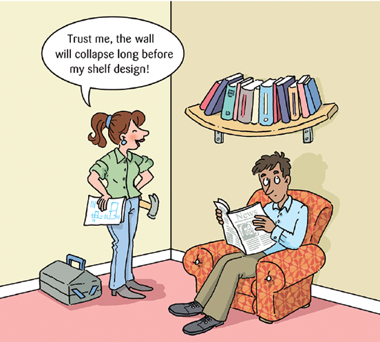
Would any of the readers of this post feel comfortable sitting in this chair while the expert is reassuring them it is all under control?
I would struggle to believe that anyone would. You would all feel that extra support is needed in the middle of this shelf to prevent it from bending. I am also sure that most of you would intuitively think that if this construct failed, failure would either happen due to the shelf breaking in the middle or due to its connections to the metal joints fracturing as the shelf angulates relative to them due to the excessive bending.
I would challenge you to imagine a scenario where you would like to be on a construct that bends as you walk. Would you feel comfortable if a bridge bent under your feet or if, while walking in your house, the floor bent? Would you get on a chair that bends under your weight? London’s Millenium Bridge was closed for two years, two days after it was released to the public due to being wobbly. The engineers had to put much thought into making it safe by making it stiffer while not making great changes to the design.
Stiffness is linked with safety in our minds because we know that for something to break, it first has to deform, and the more it deforms, the closer it gets to failure.
During my studies, I had to present ideas of making a suspension bridge of paper and tins as long and safe as possible. We had to explain in simple terms why a long elastic bridge is unsafe, where it would fail and how making it stiffer would make it safer. My presentation is in Figre 2 below.
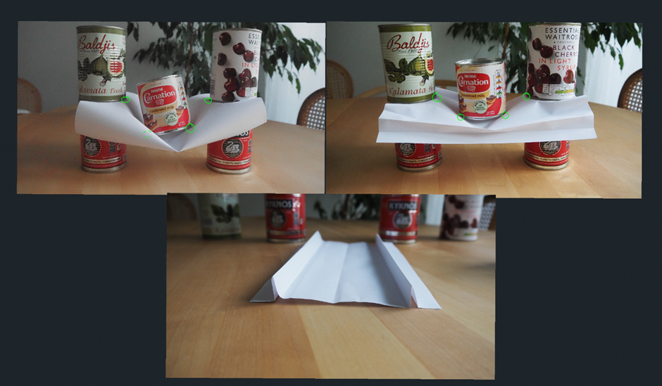
The first picture represents an unsafe suspension bridge. The paper bends excessively at the areas with the green circles. Excessive bending means excessive material strain. Also, the weight in the middle of the bridge pulls the paper towards it, and the only reason the bridge stands is the friction between the support tins on each side. If one replaces the top tins with lighter ones, the bridge will slide underneath them and fall apart. This means that in addition to the fact that the bridge is under excessive strain at the circled points, its standing depends greatly on its supports at the end.
The picture at the bottom represents my effort to make the paper stiffer at bending while making no changes to the part of the paper where the weight is applied. I did that by increasing the moment of inertia of the paper at its edges.
The picture on the right is what happens when I put the same weight on the stiffer bridge. There seems to be less bending of the paper in the circled areas. This means that there is less strain in these areas. Also, as the paper bends less, the pulling of the paper is less, which means there is less need for great friction between the support tins to keep the weight floating. In other words, there is less strain on the bridge's supports.
You can find an example of a suspension bridge in the link below.
The bridge depends on the joints at its supports. If it was screwed on concrete, this means that the screws would sustain much stress to keep the person afloat. If you and I were holding it, we would have to keep pulling with a large force each. But what would change at the joints if the bridge was stiff? Below is a stiff paper bridge.
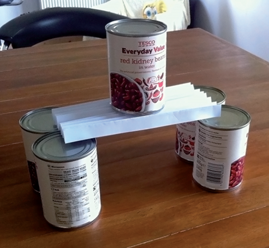
The bridge in Figure 3 does not need to be screwed on the tins, and if it were screwed on the tins, there would be very little stress on these screws. Of course, there is still stress on the tins acting as support columns. But there is no bending stress in the joint between the beam and the columns (if there was such a joint).
So, a stiffer bridge is less susceptible to fracturing and puts less stress on its joints with the support columns under three-point bending.
Now, let’s go back to the concept of elastic osteosynthesis. The illustration in the book (Figure 4) shows a similar loading to our bridges. It is a three-point bending concept. The difference is that the authors say exactly the opposite of what we saw above. They say a more elastic plate will bend more, sustaining less stress. They also say that due to the plate’s elasticity, there will be less loading on the screws which will prevent them from loosening.
Below is a representation of the book’s rationale.
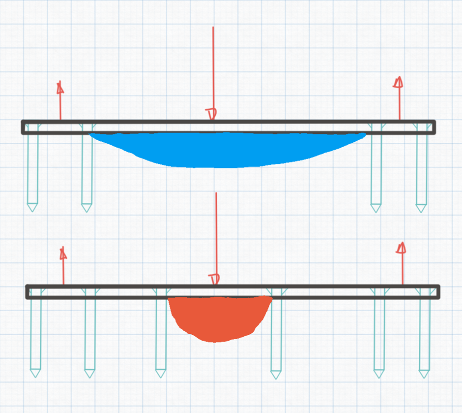
According to the book’s authors, the stress is concentrated in a shorter part of the plate with a shorter working length. This suggests that a stiffer construct is at greater risk for fracturing, which contradicts what we saw above for bridges.
The book's authors also state that there would be more stress at the screw-bone interface in the stiffer construct, which directly contradicts what we saw about suspension bridges. In addition to that, the effect of the working length on the stress at the bone around the screws has been studied (2), and it has been found to be higher in constructs with longer working lengths on axial loading. According to the authors of this study, the larger stress around screws in constructs with a long working length is due to "changes to the angle of screws during plate deformation, which increases the strain at the screw-bone interface". Look at how the bent shelf in Figure 1 is angulated relative to the metallic joints holding it. What do you think is happening to the screws holding this shelf on the metallic joints?
Lastly, can you visualise how a bone will be loaded in three-point bending during normal activities? If not, why are we studying three-point bending on plate-bone constructs?
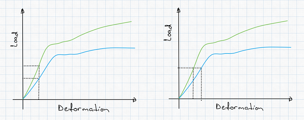
Despite all the above, I will still try to be convinced that there is a way for a stiffer plate to undergo a higher stress than a more elastic one. And, indeed, there is one. If instead of a constant load, one applies a constant deformation.
If we apply an axial load on a column, it will continue to deform until its internal load equals the external load. At this point, we say that the column is at equilibrium. If the same load is applied to a stiff and an elastic column, the elastic one will deform more, but the stress in both will be the same. That is because the stress is the distributed force over an area. If the force we applied and the cross-sectional area of both beams are the same, the stresses will be the same. But what if, instead of applying a constant load (same load on both beams), we apply a load that will create a constant deformation (same deformation on both beams)? To produce the same deformation, we will need to apply a larger load on the stiffer beam, and for this reason, the stress will be larger (the stress is the distribution of the load over an area).
Of course, that is very different from what the book's authors say. Remember that they imply that the same load will create a larger stress in the stiffer beam due to stress concentration. But maybe what they are trying to say is that the same deformation will create a larger stress in the stiffer plate. This makes sense, except we don’t induce constant deformations on plates placed into animals or humans. The muscles do not go to the bone and say, "I will deform you by 2 mm no matter how stiff you are". They must be placing them under certain loads to sustain movement. So, it makes sense that when a bone-plate construct is loaded in real life, it happens under a constant load and not a constant deformation.
All these provide no support for the concept of elastic osteosynthesis as it is described in the veterinary literature. In human literature, the terms elastic osteosynthesis and bridging osteosynthesis are interchangeable. In other words, in the human literature, they don't deliberately try to increase the elasticity of a construct. They know bridging a fracture does not provide absolute stability; hence, it is elastic.
I hope the above has provided some reassurance if you, like me, felt not smart enough to understand the concept of elastic osteosynthesis over the last 15 years. Stay tuned if you want a more detailed mechanical explanation of why this concept does not stand.
References
Moreno MR, Zambrano S, Dejardin LM, Saunders WB. Bone biomechanics and fracture biology. In: Johnston SA, Tobias KM. eds. Veterinary Surgery: Small Animal. 2nd ed. St. Louis, MO: Elsevier; 2018: 646
Alisdair R MacLeod, A Hamish R W Simpson, Pankaj Pankaj. Age-related optimization of screw placement for reduced loosening risk in locked plating. J Orthop Res. 2016 Nov;34(11):1856-1864.


Comments