_edited.png)
Elastic Osteosynthesis – The Energy approach.
- Christos Nikolaou

- Jan 26, 2025
- 6 min read
In a previous post, we tried to explain the concept of elastic osteosynthesis as described in the veterinary literature by comparing the stress and strain within a short and long beam in three-point bending. No matter how we approached this problem, we came to a different conclusion than the theory suggests.
In this post, I will make a final effort to justify how a longer beam could be advantageous compared to a shorter beam regarding resisting failure in three-point bending. For this, I will take a different approach – that of energy stored in a beam before failure. To make matters easier, I will not study what happens in three-point bending but rather in tension. That is because when a beam is bent, the material on one side is under tension and that on the other is under compression. So, studying what happens to a column under tension simplifies what happens in a beam in bending.
Let’s start with a brief discussion about energy.
Let’s assume that we want to lift a rock with a mass m off the ground to a height h. To do this, we need to apply a force F. To start moving the rock, we will need to apply a force larger than the rock’s weight mg, where g is the acceleration due to gravity. As long as we do this, the rock speeds up and lifts from the ground. Another way of looking at this is by giving rock energy, which is converted to kinetic energy by applying force F. Let’s assume that after we have given the rock some kinetic energy, we decrease the magnitude of our force to equate that of the rock’s weight. Now, the total force applied on the rock is zero. For this, its speed remains constant, and hence, there is no more kinetic energy going into the rock. That is because although we are doing some work by applying our force, the weight does the same but opposite work, cancelling us out. After a while we stop applying the force. At this moment, the rock starts decelerating due to the negative work the weight does until it momentarily stops moving. At this moment, its speed is zero, hence its kinetic energy is zero. So, has the rock’s energy disappeared? We know that the energy never disappears. It converts from one form to another. In the example above, it can be proven mathematically that the kinetic energy was converted to gravitational potential energy, which was the work done by the weight of the rock. This energy equals m x g x h. This means the rock's kinetic energy when it left the ground (when we stopped applying force F) was also m x g x h.
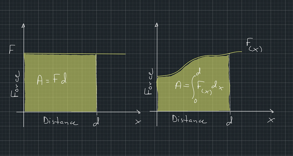
We have been talking about the work done by a force in terms of energy. It can be proven mathematically that the work done by a constant force, or else the energy transferred to an object by a constant force F, which is applied over a distance d, is W = F x d. If we produce a graph of the force as a function of the distance, the force will be represented by a straight line as it remains constant while the distance changes (Figure 1). Then, the work done by the force would be the area under the line representing the function of the force. Similarly, if the force is not constant, its work will still be the area under the line representing the function of the force (Figure 1).
Now, instead of applying a force to a rock, let’s assume that we are applying a slowly increasing force to a column, which creates tension (Figure 2). This resembles the force F above (except it is not constant). The column will apply an opposite, gradually increasing force P, tending to resist tension. The latter resembles the weight of the rock (except it is not a constant). We will assume that we are increasing force F very slowly into tiny increments such that P = F so that the column stretches with a constant speed. We stop applying the force just before the column starts to permanently deform (yield point). If you haven’t guessed, we will try to calculate the energy stored in the column due to the work done by P. This is equivalent to the elastic potential energy stored in a spring and is analogous to the gravitational potential energy we saw above.

Figure 2 shows the columns and their load-displacement curves of a long and a short column of the same dimensions made of the same material. The long column is more elastic, and the short one is stiffer. This means that the long column will displace more under the same load.
The work done by force P is stored in the columns as potential energy.
This energy can be calculated by the area under the curves, and it represents the resilience of a construct. As the areas are contained within triangles, they can be calculated as:
A = ½ x base x height.
Hence,
A1 = ½ x Δl1 x P, and
A2 = ½ x Δl2 x P.
As Δl1 > Δl2, it follows that A1 > A2.
This means that the longer, more elastic column will absorb more energy before failing.
Why is this important? Because instead of a rock, consider a dog that jumps at a height h. We saw that the gravitational potential energy after a jump to a height h is proportional to h, and that it equals the kinetic energy when leaving the ground. The latter is the energy the dog’s body received to lift from the ground, and part of it ‘travelled’ through the implant.
An implant that can absorb more energy before failure will forgive higher jumps.
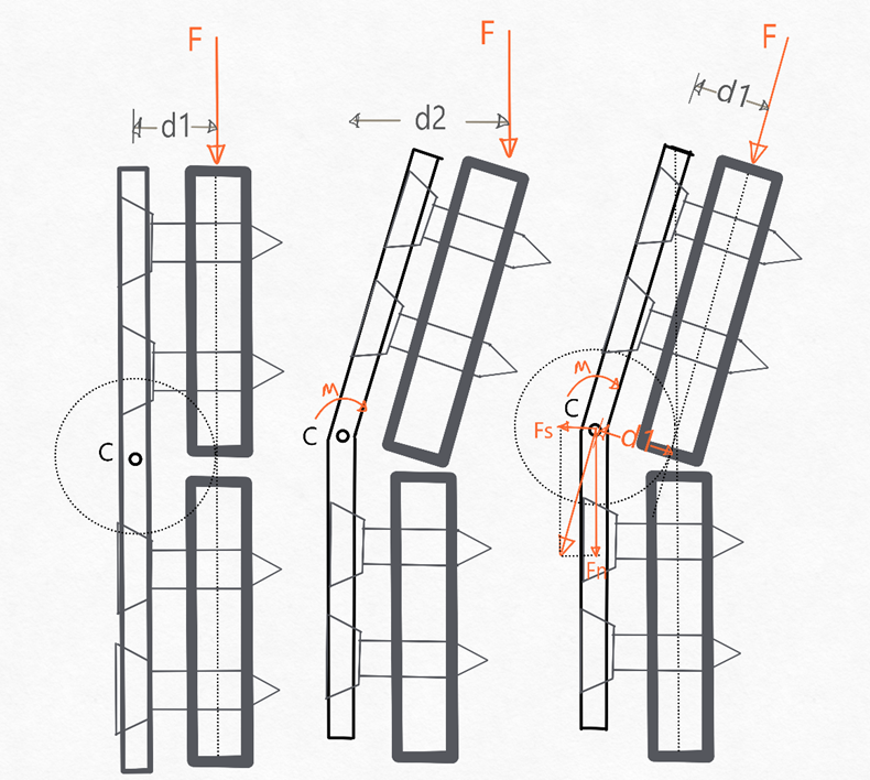
So, from an energy perspective, it would make sense to use an implant with a longer working length. However, this is a theoretical concept that does not consider many other factors, like the fact that when an implant bends more under an axial load, the moment generated by the force increases, creating larger stresses in the implant (Figure 3).
From all the above, it is very likely that when the authors say that the stress will be distributed over a larger length in a longer implant, they mean that the energy will be distributed over more material. However, although this is true, it does not mean a longer implant will better resist failure.
We have looked at the concept of elastic osteosynthesis from many different perspectives, and although we may have found what the authors may mean, the concept ignores many important variables. In following posts, we will explore the mechanics of bending beams and how the working length affects them more rigorously, and we will go through some of the literature.


Comments