_edited.png)
Joint reaction force – An introduction using the TPLO paradigm.
- Christos Nikolaou

- Feb 1, 2025
- 6 min read
The joint reaction force is an essential concept in biomechanics. Researchers in human medicine want to know its magnitude to understand the load on the cartilage of various joints during various activities. It is also important for the design of implants that need to withstand daily activities.
In veterinary orthopaedics, an example of the significance of the joint reaction force are the tibial osteotomies designed to stabilise the cranial cruciate ligament-deficient joints. However, contrary to human research, we are not interested in the magnitude of the force for this problem. We are interested in its direction.

The TPLO technique was initially intended to stabilise the joint by rotating the tibial plateau to be perpendicular to the tibial mechanical axis (1). This must have been based on the assumption that the joint reaction force is aligned with this axis. On the contrary, the TTA technique assumes that the joint reaction force is parallel to the patellar tendon when the joint is in extension (2). Researchers, unable to comprehend how these two techniques achieve the same result, looked for similarities (3). They found that both the TPLO to a TPA of 6o and the TTA technique result in similar patellar tendon angles, suggesting that the TPLO may stabilise the stifle joint through both mechanisms. That is by making the tibial plateau approximately perpendicular to the tibial mechanical axis and the patellar tendon.
More specifically, the above researchers found that a patellar tendon angle of 90o, measured using the common tangent, can be achieved by performing a TPLO to a TPA of 12o (3). However, if we measure the patellar tendon angle using the tibial plateau and not the common tangent, then a TPLO to a TPA of approximately 6o results in a patellar tendon angle of approximately 90o. So, if we don’t use the common tangent, performing a TPLO to 6o will also achieve a patellar tendon angle of 90o. However, this contradicts what the TTA technique represents (2) and the fact that all users of the TTA use the common tangent to get clinical results.
A legitimate question would be how did we get from targeting a TPA of 0o (1) to 6.5o (4) or 5o (5) in the TPLO technique? Why do different researchers choose to study different TPAs? Why did Slocum et al. first suggest an angle of 0o (1) but then change their mind to an angle of 5o (6)? After all, did they or did not believe that the joint reaction force is colinear with the tibial mechanical axis?
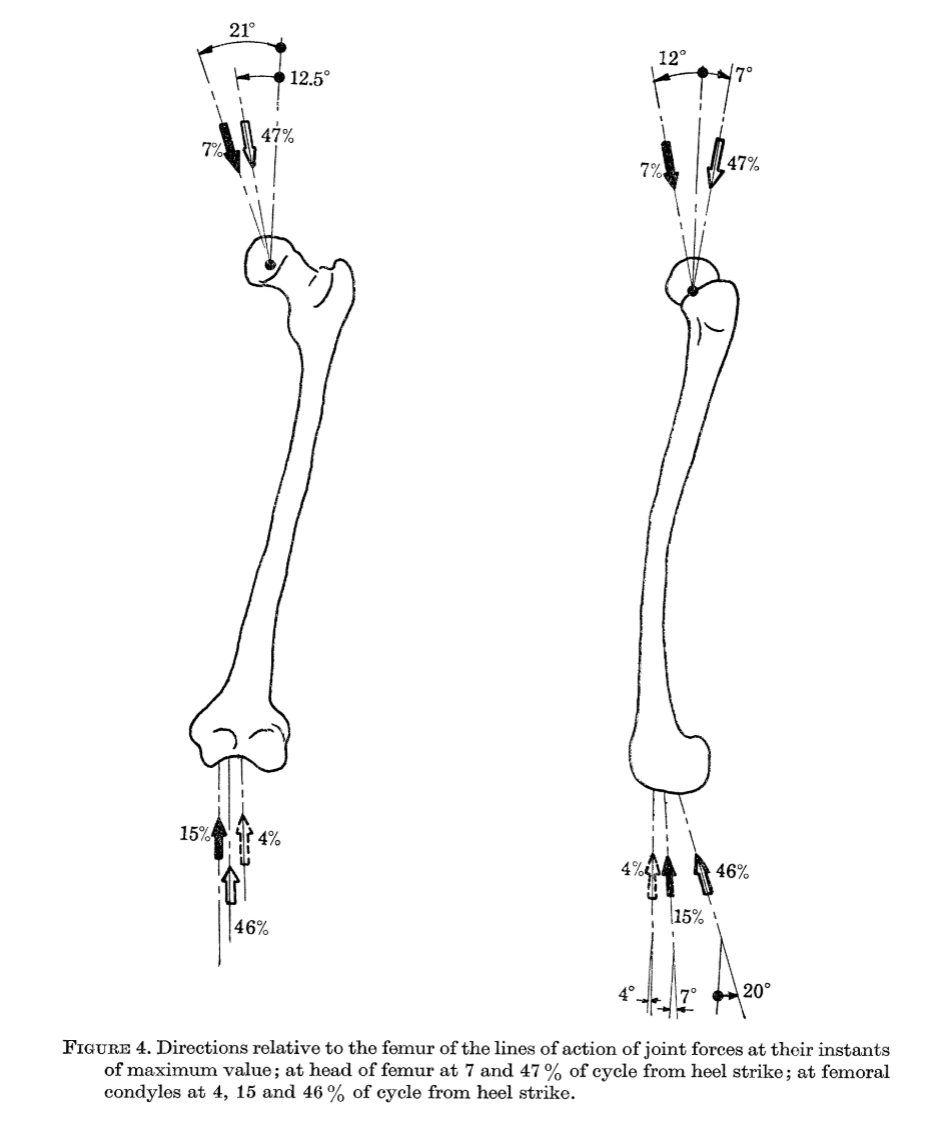
It gets so complex that it becomes obvious that something is fundamentally wrong with all the above. The most likely problem is the assumptions on the joint reaction force. It must not be collinear to the mechanical axis nor parallel to the patellar tendon. Indeed, looking at the human literature, statements such as the above would look mythical. That is because the joint force is studied using the most rigorous ways of mathematical approximations (optimisation), and there is no reason for an engineer to assume that the joint force is in a specific direction. The first work on finding the joint forces in the human body was done in 1976 (7). Since then, mathematical methods and data recording methodologies have evolved substantially. Nevertheless, this first work was ground-breaking and set the way for the ones that followed.
One may wonder where the assumption that the joint reaction force is parallel to the patellar tendon is based. The reference the authors use in the study (2) is the manuscript (8) below. Nowhere in this article do the authors state or suggest such a thing. Moreover, their study is on people sitting on a chair extending their knee joint while lifting a weight attached to their ankle. This is different from what happens during walking, where the ground reaction force is at play. If you wonder why Slocum et al. assumed the joint reaction force is collinear with the tibial mechanical axis, I can only assume that this is because “mechanical” suggests that a force is going through it. But we don’t care what happens within the tibia. We want to know what happens at the surface of it. This is where the femur and the tibia slip on each other.
But TPLO works. Some say that TTA also works.
So, although the assumptions the techniques are based on have no rational justification, they must not be far from the truth. Slocum et al.'s intuition seems to have worked well. As you may have assumed, to understand what the joint reaction force is, we will need some fundamental mechanical knowledge. This will be the subject of the next post.
How is it possible that there are no studies on the canine knee joint reaction force? Actually, this has been studied. Shahar R and Banks-Lills L (9,10) used the most current methodology for determining the force in a dog. It was not perpendicular to the tibial plateau nor parallel to the patellar tendon. Ron Shahar is a mechanical engineer with a master's in applied mathematics and a board-certified small animal surgeon. Banks-Lills L is a materials engineer. We will need to translate their math into English. So, we will.
Stay tuned!
1. Slocum, B. and Slocum, T.D. (1993) Tibial plateau leveling osteotomy for repair of cranial cruciate ligament rupture in the canine. Veterinary Clinics of North America: Small Animal Practice, 23 (4), pp. 777-795.
2. Kipfer NM, Tepic S, Damur DM et al (2008) Effect of tibial tuberosity advancement on femoro-tibial shear in cranial cruciate-deficient stifles. Vet Comp Orthop Traumatol, 21, pp 35-390
3. Drygas KA, Pozzi A, Goring RL et al (2010) Effect of tibial plateau levelling osteotomy on patellar tendon angle: a radiographic study. Veterinary Surgery, 39, pp 418-424.
4. Warzee CC, Dejardin LM, Arnoczky SP et al (2001) Effect of titibal plateau leveling on cranial and caudal tibial thrusts in canine cranial cruciate-deficient stifles: an in vitro experimental study. Veterinary Surgery, 30, pp 278-286
5. Reif U, Hulse DA, Hauptman JG (2002) Effect of tibial plateau leveling on stability of the canine cruciate-deficient stifle joint: an in vitro study. Veterinary Surgery, 31, pp. 147-154.
6. Slocum B, Slocum TD (1998) Tibial plateau leveling osteotomy for cranial cruciate ligament, in Borjab MJ (ed): Current Techniques in Small Animal Surgery (ed 4), Baltimore, MD, Williams and Wilkins, pp. 1209-1215.
7. Paul JP (1976) Force actions transmitted by joints in the human body. Proc R Soc Lond B, 192, pp.163-172
8. Ralph N (1985) Mechanics of the knee. A study of joint and muscle load with clinical applications. Act orthopaedical Scandinavica supplementum no. 216, Vol 56.
9. Shahar R, Banks-Sills L (2004) A quasi-static three-dimensional, mathematical, three-body segment model of the canine knee. Journal of Biomechanics, 37, pp. 1849-1859.
10. Shahar R, Banks-Sills L (2002) Biomechanical analysis of the canine hind limb: calculation of forces during three-legged stance. The Veterinary Journal, 163, pp. 240-250.


Comments